Two‑Handed Fly‑Rod Overhead Surf CastingA mechanical doctrine for overhead castingBy Mark Severino
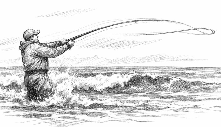
This work stands on the foundation built by the innovators who explored two‑hand rods in saltwater long before the mechanics were ever formalized.Their experimentation, whether in surf, estuaries, or open beaches, proved that long rods could generate speed, carry, and distance beyond the limits of single‑hand tackle.Although their contributions were never documented as a unified system, their willingness to push tools and techniques outside traditional Spey frameworks created the space in which this doctrine could finally emerge.What Overhead Surf Casting Actually IsTwo-Handed Fly Rod Overhead Surf Casting is a distance-driven casting discipline built around a two-handed fly rod, an intermediate shooting head, and a straight-line overhead stroke designed to cut through wind, surf turbulence, and down-beach current.It is not Spey casting. It is not single-hand overhead casting. It is its own mechanical system.Why Surf Requires Its Own MechanicsSurf conditions break every assumption of river or lake casting:
• the head drifts down beach
• the leader pulls off axis
• waves push and pull the line
• the intermediate head sags underwater
• tension collapses
• alignment breaksA standard overhead pickup fails immediately.
Surf requires:
• aerialized tensioning
• a straight casting lane
• a high apex
• a tension-preserving slide
• late rotation
• a wind-cutting loopThis is why overhead surf casting with a two-handed fly rod must be treated as a separate discipline.The Casting Lane
The casting lane is:
• a straight corridor
• 24–30 inches wide
• directly in front of your casting shoulder
• the path both the backcast and forward cast must followIf the line is not in the lane, the cast collapses. The entire discipline is built around restoring and preserving this lane.
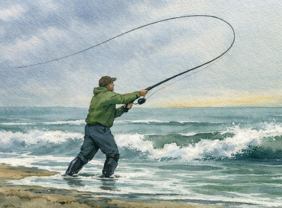
Surf Hydrodynamics & Aerialized TensioningSurf destroys tension through four forces:
1. Down Beach Current
Pulls the head sideways and off axis.2. Trough Pull
Sucks the line forward, creating slack.3. Intermediate Head Sag
Density drags the head underwater.4. Surface Turbulence
Waves push and pull the system unpredictably.Result: You cannot begin an overhead stroke from this position, especially with a two-handed fly rod, which requires a straight, tensioned system to load correctly.You must retension and realign the line first, and it must be aerialized.
Why Retensioning Must Be AerializedWaterborne retensioning fails because:
• the head sticks
• the leader drags
• the fly pulls sideways
• the rod loads late
• the apex collapsesAerialized retensioning:
• removes water drag
• straightens the system
• realigns the fly
• restores the casting lane
• sets tension
• sets the apex
• sets the rod loadThis is the only way to prepare a two-handed fly rod for a clean overhead backcast in surf.The Aerialized Retensioning Sequence
Lift → Aerialized Snake Roll Pickup → Aerialized Roll Cast Pickup1. The Lift
• rod tip rises
• head comes off the water
• slack disappears2. Aerialized Snake Roll Pickup
• tight forward-biased
• line flips forward in the air
• line/fly parallel with casting lane3. Reverse Snake Roll Pickup
Used when wind or current forces off shoulder alignment.4. Aerialized Roll Cast Pickup
• head is already airborne
• rod simply straightens the system
• tension and apex are setThis is the bridge to the overhead stroke.
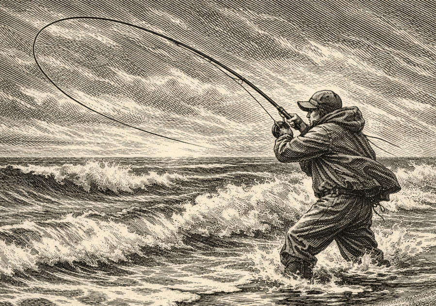
The Pure Overhead Stroke (Apex + Slide + Late Rotation)The Two-Handed Fly Rod Stroke EngineThe overhead surf stroke is a four-phase mechanical system:1. The Lift
Removes slack and extracts the head.2. The High Backcast
Rod travels up and back, stopping high to set an 8–12 ft apex.3. The Slide
A tension-preserving forward slide that:
• keeps the apex from collapsing
• keeps the rod loaded
• keeps the line in the casting lane4. The Forward Stroke
Translation - Late Rotation (bottom hand driven)
• butt drives forward first
• rotation happens late
• loop compresses
• line speed spikes
• wind penetration increasesThe rod translates forward along a straight rail, then the bottom hand pulls to deliver late‑rotation power that tightens the loop and drives the line through the wind.This is the only stroke that produces 90–100 ft with a two-handed fly rod in surf.Apex Theory
Apex height determines your distance ceiling:
• Low apex (4–6 ft) → 60–75 ft
• Mid apex (6–8 ft) → 80–90 ft
• High apex (8–12 ft) → 90–100 ftThe apex is controlled by:
• backcast trajectory
• stop height
• tension from retensioning
• the slide
• line densityThe apex is the heart of overhead distance.
Late Rotation Mechanics
Late rotation is the difference between:
• 75 ft (early rotation)
• 95 ft (late rotation)Mechanics:
• translation first
• rotation last
• loop tightens
• line speed increasesEarly rotation dumps energy. Late rotation stores and releases it at the perfect moment.
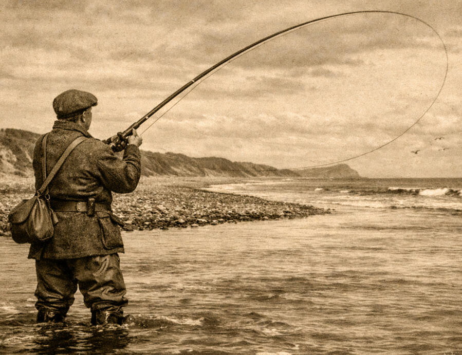
System Design & Surf ApplicationBuilding and Using the Two-Handed Fly Rod SystemSystem Design
Rod
• 10–14 ft two-handed fly rod
• fast recovery
• stiff butt section
• optimized for overhead loadLine
• intermediate head for stability
• grain window matched to rodLeader
• intermediate or medium sink
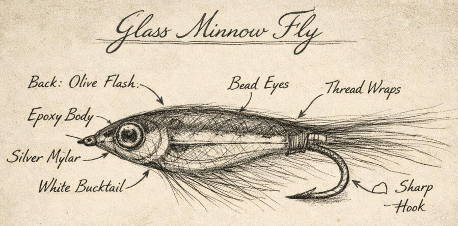
• density to stabilize the flyFly
• aerodynamic
• sparse
• minimal frontal areaThis is the complete 100 ft system build.Surf Application
0–2 ft Surf
• easiest casting window
• minimal turbulence
• maximum distance potential2–4 ft Surf
• requires stronger retensioning
• apex must be higher
• slide becomes mandatory15–25 mph Wind
• lower forward trajectory
• tighter loop
• heavier leader densityLine Management in Waves
• strip high
• avoid trough pullFishing the 2–3 ft Micro Bait Band
• the most productive depth
• intermediate head + sparse fly
• long, straight presentation
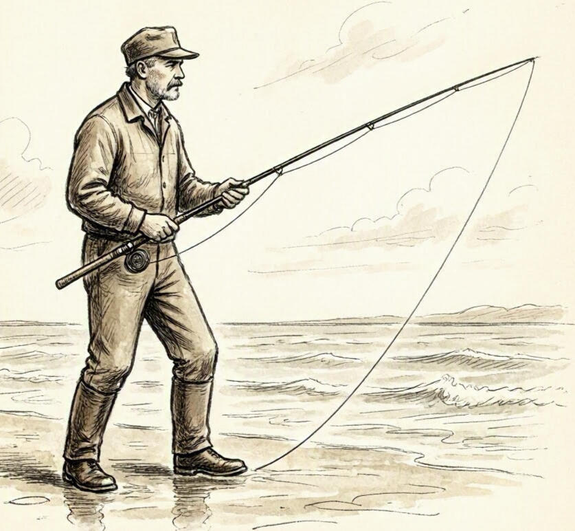
THE APEXHow Apex Height, Apex Stability, and Apex Timing Control the Entire Overhead Surf CastWhat the Apex Actually IsThe apex is the highest point of the backcast loop during a two-hand overhead surf cast.
It is:
• the vertical peak of the line
• directly in the casting lane
• 6–12 feet above the water
• fully tensioned
• fully airborne
• fully alignedApex height determines your distance ceiling.
The apex is the structural foundation of the entire overhead stroke.Why the Apex Matters
The apex controls:
• distance
• loop shape
• line speed
• tension
• wind penetration
• slide stability
• forward stroke timingIf the apex is wrong, the cast collapses, even if everything else is perfect.Apex Height ZonesLow Apex (4–6 ft)
• collapses in turbulence
• loses tension
• dumps energy
• 60–75 ft ceilingMid Apex (6–8 ft)
• stable in light surf
• holds tension
• moderate wind penetration
• 80–90 ft ceilingHigh Apex (8–12 ft)
• clears turbulence
• maximizes tension
• stabilizes the slide
• enables late rotation
• 90–100 ft ceilingAerialized Re-tensioning & The Initial PullSurf destroys tension through:
• down beach drift
• trough pull
• intermediate head sag
• turbulence
You cannot begin a backcast from this position.The system must be pretensioned in the air, not on the water.The Initial Pull
The initial pull is the moment when:
• the airborne system straightens
• tension spikes
• the rod tip is pulled forward
• the rod preloads
• the casting lane is restoredThis micro load event is the engine that builds the apex.
No initial pull → no apex.Aerialized Anchor Geometry (Variable Length System)
Your full system is:
• 30 ft intermediate head
• 10 ft Polyleader
• 3 ft tippetMaximum airborne length: 43 ft
But this only occurs when the entire head is outside the rod tip.If you are not carrying the full head, the airborne system is shorter:
• 25 ft head out → 38 ft system
• 20 ft head out → 33 ft system
• 15 ft head out → 28 ft system
The system length is dynamic, not fixed.The aerialized Snake Roll Pickup flips the system forward so that whatever portion of the head is outside the rod tip, plus the Polyleader and tippet, straightens fully airborne in the casting lane, directly in front of the casting shoulder.When the system straightens, tension spikes, the rod pre-loads, and the initial pull forms. This is the position from which the high backcast apex is built.Backcast Stop Height (Apex Stop Window: 1:30–2:00)Apex height is controlled by the rearward stop angle of the backcast. To produce an 8–12 ft apex in surf conditions, the rod must stop in a high, slightly back-biased window.Correct Stop Window for a High Apex:Clock Face Geometry
• 12:00 — straight up
• 1:00 — slightly back
• 1:30 — deeper back, apex valid
• 2:00 — perfectWhy 2:00 WorksThis window:
• drives the backcast up and back
• sets the apex above turbulence
• preserves tension
• prevents tip dip
• stabilizes the slide
• enables late rotation
• produces the 8–12 ft apex required for 90–100 ft castsThis is the only stop window that consistently produces:
• a stable high apex
• a tensioned slide
• a late rotation power stroke
• maximum distance potentialHow the Apex Is CreatedApex height is determined by four mechanical inputs:1. Backcast Trajectory
Rod tip travels up and back, not sideways.2. Stop Height
Rod tip stops in the 2:00 window.3. Aerialized Re-tensioning
The airborne system is:
• straight
• tensioned
• aligned
• ready to load
before the backcast begins.4. The SlideThe forward slide preserves:
• apex height
• tension
• rod load
The slide is the apex stabilizer.Apex Stability: The Four Failure ModesApex Timing: The Hidden Engine of DistanceApex timing is the moment when:
• the backcast straightens
• tension peaks
• the slide begins
• the rod stays loaded
• the forward stroke initiatesIf you rotate before the apex straightens → early rotation → 70–80 ft.
If you rotate after the apex straightens → late rotation → 90–100 ft.
This timing window separates average casters from distance casters.Apex Collapse:
1. backcast is too low
2. stop is too soft
3. slide is too short
4. line is not tensioned
5. head is too long or too lightWhen the apex collapses:
• tension disappears
• the rod unloads
• the loop opens
• the cast dies at 40-50 ft
Apex collapse is the #1 cause of failed surf casts.Apex RecoveryIf the apex collapses:
• lengthen the slide
• raise the forward trajectory
• delay rotation
These corrections restore tension and allow the cast to recover.The Apex Doctrine
1. Apex height controls distance.
4–6 ft → 60–75 ft; 6–8 ft → 80–90 ft; 8–12 ft → 90–100 ft2. Apex stability depends on a fully tensioned airborne system.
System length = 28–43 ft, depending on the amount of head carried.3. The initial pull is created when the airborne system straightens.
This pre-loads the rod and builds the apex.4. The apex is built from a fully airborne, tensioned system.
No water contact. No Spey anchor.5. The apex stop window is 2:00
This is the only geometry that produces a stable high apex.6. The apex is the heart of the overhead surf cast.Everything else — slide, stroke, loop — depends on it.
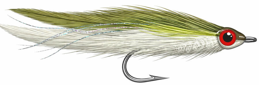
DRIFT AND SLIDEA MECHANICAL ANALYSIS OF POSITIONING MOVES WITH THE TIP RIDING A LEVEL PLANEPurpose of Drift and Slide
Drift and slide are positioning moves, not power moves. Their
function is to:1. Set the rod in the correct geometric position for the forward stroke.2. Preserve the forward stroke plane by preventing tip drop or tip rise.3. Control stroke length without adding force.4. Establish the correct launch height for the intended cast.When executed correctly, drift and slide create a neutral, stable, level tip position from which the forward stroke can begin without compensation.DefinitionsDrift
A lift and place movement performed after the backcast straightens. It repositions the rod to a higher, more advantageous starting point for the forward stroke.
Key characteristics:
• No rotation added
• No acceleration added
• No tension added
• Pure repositioningSlide
A short, level, forward translation of the rod tip performed after drift and before rotation. It lengthens the stroke without altering the tip’s vertical plane.Key characteristics:
• Level tip path
• No rotation
• No power
• Micro translation onlyThe Level Plane Requirement
The rod tip must ride a single, horizontal plane from the end of drift through the end of slide.This prevents:
• Tip drop (causes early load and tailing tendencies)
• Tip rise (causes loss of load and open loops)
• Plane shift (forces compensatory rotation)A level plane ensures the forward stroke begins from a stable, neutral, repeatable geometry.Mechanical SequenceThe correct sequence is:
1. Backcast straightens
2. Drift (lift and place to the desired height)
3. Pause (micro pause; line straightens and stabilizes)
4. Slide (short, level, forward translation)
5. Forward stroke (acceleration → rotation → stop)Each step has a distinct mechanical purpose and must not be blended.Drift Mechanics
Height
Drift height determines:
• Launch apex
• Stroke length
• Distance potential
Higher drift = higher apex = longer carry and greater distance.Path
Drift must be:
• Upward
• Slightly rearward
• Zero rotation
• Zero acceleration
The rod is simply placed into position.Timing
Drift occurs after the backcast straightens. If drift is performed early, it becomes part of the backcast and alters load timing.Slide MechanicsSlide increases stroke length without altering:
• Tip height
• Tip plane
• Load timing
It is a pre-load positioning move, not a loading move.Length
For most rods:
• 1 inch to 2 inches is correct
• Longer slides introduce instability
• Shorter slides reduce stroke lengthPath
The slide must be:
• Level
• Straight
• Forward
• Zero rotation
Any deviation introduces tip path errors.Why Drift and Slide Must Be SeparateDrift sets height. Slide sets stroke length.If combined:
• Height becomes inconsistent
• Stroke length becomes inconsistent
• Plane control is lost
• Forward stroke timing becomes unpredictable
Separating the two creates a repeatable, modular sequence.Common ErrorsDrift with rotation
Creates an early load and destroys the forward-stroke geometry.Slide with tip drop
Forces compensatory lift during the forward stroke.Slide that is too long
Introduces slack and delays load timing.No slide
Shortens stroke length and reduces distance.Distance ImplicationsDistance is governed by:
• Drift height
• Slide length
• Plane control
• Apex angle
• Late rotationDrift sets the apex. Slide sets the stroke length. Both must be correct before the forward stroke begins.
Bottom LineDrift and slide are precision positioning moves that determine the geometry of the forward stroke. When the rod tip rides a level plane from drift through slide, the forward stroke begins from a stable, repeatable, mechanically correct position.This is the foundation of consistent, high-apex, long-range overhead casting.
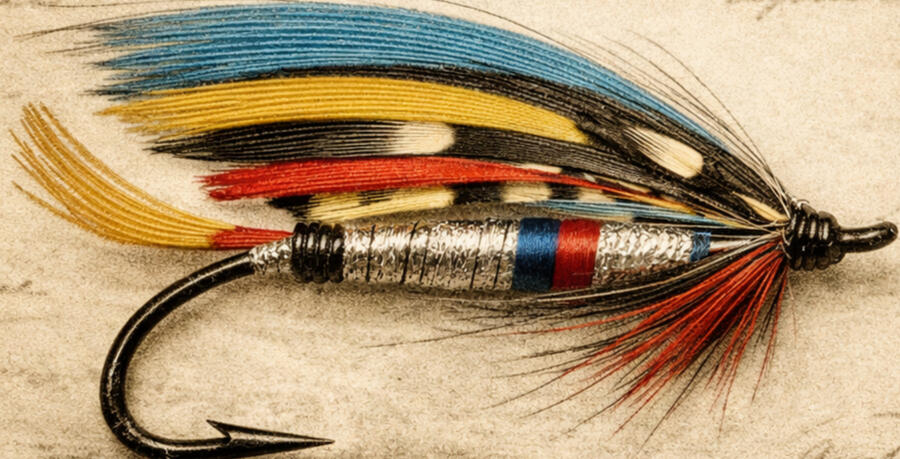
THE FORWARD STROKE TRANSLATION PHASEWhat Happens Immediately After Slide, and How Translation Begins1. Transition From Slide to Translation
Slide is the final positioning move of the cast.
It is a short, level, forward micro‑movement (1–2 inches) that sets the stroke length without loading the rod or changing its angle.When slide ends:The rod tip is forward.The rod tip is level.The rod angle is unchanged.The rod is unloadedThe line is straight and under tension.The forward‑stroke plane is established.This is the start position for translation.There is no overlap between slide and translation.
Slide ends completely before translation begins.2. What Happens Immediately After Slide
The moment the slide ends, the caster begins translation, the first movement of the forward stroke.This transition is defined by one change:The rod begins moving forward in a longer, level, non‑rotational path that initiates the forward stroke but does not yet load the rod.
This is the beginning of translation.3. The First Inch of Translation
The beginning of translation has these characteristics:Both hands move forward together.The rod angle remains frozen.The rod tip stays on the same level plane established by drift and slide.The rod does not bend.The line remains under tension.The movement is longer than slide and now part of the forward stroke.This is the first inch of translation and the defining moment where the cast transitions from positioning to stroke mechanics.4. Why This Movement Is Translation and Not Slide
Although the rod is still moving forward and still level, the movement is now:LongerSmootherPart of the forward strokeDesigned to establish linear accelerationPreparing the rod for load timingNo longer a micro‑adjustmentSlide = micro‑positioning
Translation = macro‑stroke initiationThe difference is scale, purpose, and timing.5. The Mechanical Purpose of This Transition
The beginning of translation:Preserves the level‑plane tip pathMaintains tension without loading the rodExtends the stroke length beyond the slideEstablishes the linear acceleration curveSets the rod in the correct geometric path for rotationPrevents early loadPrevents slackCreates the conditions for late rotation and tight loopsThis is the most misunderstood part of the overhead stroke, and the most important for distance.6. Translation Length and Rod Length
The beginning of translation is identical across rods, but the total translation length varies:12–13 ft rods: 4–6 inches13.7–14 ft rods: 6–8 inches14.8–15 ft rods: 8–10 inchesBut the first inch of translation is always the same:
Forward, level, non‑rotational, tension‑preserving.Bottom Line
After slide, you begin translation by moving the rod forward in a longer, level, non‑rotational path that initiates the forward stroke but does not yet load the rod.This is the exact moment where:Positioning endsThe forward stroke begins.Linear acceleration startsLoad timing is established.The cast transitions toward rotation.This is the bridge between slide and rotation, and it is essential for apex height, loop shape, and maximum distance.
ROTATION MECHANICSThe Angular Acceleration Phase Driven by the Lower Hand Pull1. Position in the Stroke Sequence
Rotation is the fifth element in the two-handed overhead sequence:
1. Backcast straightens
2. Drift
3. Slide
4. Translation
5. Rotation (with lower hand pull)
6. Stop
7. Recovery
Rotation begins only after translation is complete.2. Purpose of Rotation
Rotation is the power phase of the forward stroke. Its purpose is to:
• Load the rod
• Accelerate the line
• Form the loop
• Set the apex
• Deliver the cast
Translation sets the geometry. Rotation delivers the energy.3. When Rotation Begins
Rotation begins the instant:
• Translation has reached its forward limit
• The rod is still unbent
• The line is still under tension
• The rod tip is still level and on plane
• The caster initiates lower hand pull
This is the load point.4. The Lower Hand Pull (Core of Rotation)
The pull is the mechanical driver of rotation. It is not a separate phase. It is the method by which rotation occurs.What the Pull IsThe pull is:
• A downward and inward movement of the lower hand
• Occurring during the steepest part of the rotation curve
• Creating angular acceleration around the upper hand
• Loading the rod late
• Driving the tip through a tight, level arc
The upper hand acts as a pivot and stabilizer, not a pusher.What the Pull DoesThe pull:
• Initiates rod bend
• Accelerates the rod tip
• Tightens the loop
• Raises the apex
• Increases line speed
• Maximizes distance
The pull is the engine of the forward stroke.What the Pull Is NOTThe pull is not:
• A downward chop
• A body-driven yank
• A push with the top hand
• A blended translation
• A drift
• A slide
It is a late, crisp, angular acceleration.5. The Rotation CurveRotation follows a late, steep acceleration curve:
• Slow at initiation
• Lower hand pull begins
• Speed increases rapidly
• Maximum acceleration just before the stop
• Abrupt termination at the stop
This curve:
• Loads the rod efficiently
• Produces tight loops
• Maximizes line speed
• Maximizes apex height
• Maximizes distance
Early rotation or early pull destroys all of these.6. The StopRotation ends in a hard, abrupt, high stop.The stop:
• Transfers stored energy into the line
• Forms the loop
• Sets the apex
• Determines loop geometry
• Determines distance
The stop is the end of rotation and the birth of the loop.7. Plane Control During RotationRotation must occur on the same level plane established by:
• Drift
• Slide
• Translation
Any deviation (tip dip, tip rise, off-plane pull) forces compensatory movement and degrades the loop shape.
Plane integrity is non-negotiable.8. Rod Length and Rod Action Considerations12–13 ft rods
• Shorter rotation arc
• Faster pull speed
• Sensitive to early pull
• Lower apex potential13.7–14 ft rods
• Longer rotation arc
• More stable under load
• Higher apex potential
• Better distance ceiling14.8–15 ft rods
• Longest rotation arc
• Most stable under load
• Highest apex potential
• Maximum distance capability
Rotation length scales with lever length.9. Common ErrorsEarly Pull / Early Rotation
• Rod loads too soon
• Loop collapses
• Apex drops
• Distance lostSlow Pull
• Open loops
• Low apex
• Poor wind penetrationTip Dip During Pull
• Tailing tendencies
• Collapsed loopNo Stop
• Energy leaks
• Loop fails to form
• Distance collapses10. Distance ImplicationsRotation is the primary determinant of:
• Loop tightness
• Line speed
• Apex height
• Distance ceilingCorrect rotation produces:
• Late load
• Tight loops
• High apex
• Maximum line speed
• Maximum distance
Incorrect rotation reduces distance by 20–30 ft depending on rod length.Bottom Line
Rotation is the late, lower hand-driven pull that loads the rod, forms the loop, and delivers the cast.It must begin only after translation is complete and must end in a crisp, high stop.
THE STOP MECHANICSThe Abrupt Termination of Rotation That Transfers Energy, Forms the Loop, and Sets the Apex1. Position in the Stroke Sequence
The stop is the sixth element in the two-handed overhead sequence:
1. Backcast straightens
2. Drift
3. Slide
4. Translation
5. Rotation (lower hand pull)
6. Stop
7. Recovery
The stop is the end of rotation and the moment the loop is born.2. Purpose of the Stop
The stop has three non-negotiable functions:
1. Terminate rotation abruptly
2. Transfer stored energy from the rod into the line
3. Define loop geometry and apex heightWithout a clean stop, the cast cannot produce:
• Tight loops
• High apex
• Maximum line speed
• Maximum distance
The stop is the single most important moment in the entire forward stroke.3. What the Stop Is
The stop is:
• A hard, abrupt, high position termination of rotation
• With zero drift, zero collapse, zero follow-through during the stop itself
• Occurring at the exact moment of maximum rod bendThe stop is not a pause. It is not a deceleration. It is not a soft landing.
It is a mechanical brake.4. What the Stop Does to the Rod
At the stop:
• The rod is fully bent
• Rotation ceases instantly
• The rod unloads
• Stored elastic energy transfers into the line
• The tip rebounds upward
• The loop forms
The stop is the trigger for rod unloading.5. What the Stop Does to the Line
The stop:
• Forces the line to overtake the rod tip
• Creates the top leg of the loop
• Creates the bottom leg of the loop
• Defines loop width
• Defines loop speed
• Defines apex height
The stop is the birth of the loop.6. Stop Height
Stop height determines:
• Apex height
• Loop trajectory
• Distance potentialHigh stop
• High apex
• Long carry
• Maximum distance
• Best wind penetrationLow stop
• Low apex
• Shorter carry
• Reduced distance
Surf overhead casting requires a high stop.7. Stop Plane
The stop must occur on the same level plane established by:
• Drift
• Slide
• Translation
• RotationAny deviation (tip dip, tip rise, off-plane stop) degrades the loop geometry.
Plane integrity is mandatory.8. Lower Hand Behavior at the Stop
The lower hand:
• Finishes its pull
• Stops abruptly
• Does not drift
• Does not collapse
• Does not continue downward
The lower hand is the brake.9. Upper Hand Behavior at the Stop
The upper hand:
• Acts as a pivot
• Holds the rod in the stop position
• Does not push
• Does not drift forward
• Does not collapse backward
The upper hand is the anchor.10. Common ErrorsSoft Stop
• Rod unloads slowly
• Loop opens
• Apex drops
• Distance collapsesLow Stop
• Low apex
• Poor wind performance
• Short carryOff Plane Stop
• Twisted loop
• Inconsistent turnoverStop With Drift
• Energy leaks
• Loop fails to form cleanlyNo Stop
• No loop
• No apex
• No distance11. Distance ImplicationsThe stop is the primary determinant of:
• Loop tightness
• Apex height
• Line speed
• Distance ceilingA correct stop produces:• Tight, wind-cutting loops
• High apex
• Maximum line speed
• Maximum distance
A poor stop reduces distance by 20–40 ft depending on rod length.Bottom Line
The stop is the abrupt, high position termination of rotation that transfers stored energy into the line, forms the loop, and sets the apex. It is the most critical single moment in the forward stroke.A clean stop = tight loop, high apex, maximum distance. A soft or low stop = collapsed loop, low apex, lost distance.
FOLLOW THROUGH MECHANICSThe Post Stop Rod Path That Stabilizes the Loop, Manages Rebound, and Preserves Apex Height1. Position in the Stroke SequenceFollow-through is the seventh and final element in the two-handed overhead sequence:
1. Backcast straightens
2. Drift
3. Slide
4. Translation
5. Rotation (lower hand pull)
6. Stop
7. Follow Through
The follow through occurs after the stop, once the loop has already formed.2. Purpose of the Follow ThroughThe follow through has three mechanical purposes:
1. Stabilize the rod tip after the stop
2. Manage rod rebound so it does not distort the loop
3. Preserve the apex height and trajectory established by the stop
The follow through does not add power. It does not change loop shape. It does not influence load.
Its job is stability, not energy.3. What the Follow Through IsThe follow through is:
• A controlled relaxation of the rod after the stop
• A slight upward and outward drift of the rod tip
• A stabilizing movement that prevents rebound from collapsing the loop
• A plane preserving motion that maintains trajectory
It is subtle, controlled, and deliberate.4. What the Follow Through Is NOTThe follow through is not:
• A continuation of rotation
• A power stroke
• A push
• A pull
• A downward chop
• A forward drift
• A correction
• A recovery from a bad stop
If you are “fixing” something in the follow through, the error happened earlier.5. Rod Behavior During Follow ThroughAt the stop:
• The rod is fully bent
• The rod unloads
• The tip rebounds upward
• The loop formsDuring follow through:
• The rod continues to rebound
• The caster guides the rebound
• The tip stays on the same plane
• The tip does not dip
• The tip does not rise excessively
• The rod settles into neutral
The follow through absorbs and manages the rod’s elastic rebound.6. Hand Behavior During Follow ThroughLower Hand
• Stops pulling
• Relaxes slightly
• Does not drop
• Does not drift forward
• Maintains plane integrityUpper Hand
• Holds the rod in the stop position
• Allows slight upward/outward drift
• Does not push
• Does not collapse backward
The hands stabilize, not power.7. Plane ControlThe follow through must occur on the same plane established by:
• Drift
• Slide
• Translation
• Rotation
• StopAny deviation (tip dip, tip rise, off plane drift) can:
• Distort the loop
• Collapse the apex
• Reduce distance
Plane integrity remains mandatory even after the loop is formed.8. Follow Through and DistanceThe follow through does not add distance. But it protects distance by:
• Preventing tip dip
• Preventing apex collapse
• Preventing loop distortion
• Preventing energy loss from rebound
Poor follow-through can cost 10–15 ft by collapsing the apex.
A correct follow-through preserves the cast you already made.9. Common ErrorsNo Follow Through
• Rod rebounds uncontrolled
• Tip dips
• Loop collapsesForward Drift After the Stop
• Apex drops
• Loop widens
• Distance lostDownward Follow Through
• Tailing tendencies
• Collapsed loopExcessive Upward Drift
• Loop trajectory becomes too steep
• Turnover suffersOff Plane Follow Through
• Twisted loop
• Inconsistent turnoverBottom Line
The follow through is the controlled, plane-preserving stabilization of the rod after the stop. It manages the rebound, protects the loop geometry, and preserves the apex height.It adds no power. It adds no load. It simply ensures the cast you made remains intact.
READING THE LOOP IN THE AIRDiagnosing Stroke Mechanics by Observing Loop Geometry, Speed, Stability, and Trajectory in Real Time1. Purpose of Reading the Loop
Reading the loop in the air is the primary diagnostic skill in two-handed overhead surf casting.It allows the caster to:
• Identify mechanical errors during the cast
• Correct the next cast before making it
• Understand how the rod, line, and stroke are interacting
• Maintain consistency in wind, surf, and variable conditions
The loop is the truth teller. It reveals everything the rod tip did.2. The Loop Is a Moving Report of the StrokeEvery loop carries four categories of information:
1. Geometry — width, shape, symmetry
2. Speed — turnover rate, line acceleration
3. Stability — wobble, twist, collapse
4. Trajectory — apex height, angle, flight pathThese four elements correspond directly to the four mechanical phases:
• Drift
• Slide
• Translation
• Rotation
• Stop
Reading the loop is reading the stroke.3. Geometry: What Loop Shape Tells YouA. Tight Loop (narrow V)
Indicates:
• Straight tip path
• Clean rotation
• High, abrupt stop
• Proper lower hand pull
This is the ideal surf loop.B. Open Loop (wide U)
Indicates:
• Soft stop
• Excessive forward drift
• Tip dip during rotation
• Too much upper hand push
Open loops are common with yarn fliesC. Collapsing Loop
Indicates:
• Low stop
• Late rotation
• Over rotation
• Slack in the system
A collapsing loop always means energy leaked before the stop.D. Twisted Loop
Indicates:
• Off plane rotation
• Off plane stop
• Torqued lower hand pull
Twist = plane violation.4. Speed: What Turnover Rate Tells YouA. Fast Turnover
Indicates:
• Strong load
• Clean rotation
• Abrupt stop
• Proper timing
Fast turnover is required for surf distance.B. Slow Turnover
Indicates:
• Soft stop
• Under rotation
• Weak lower hand pull
• Excessive slide
Slow turnover = lost distance.C. Overspeed Turnover
Indicates:
• Too much rotation
• Too much power
• Tip path too steep
This produces a loop that snaps over aggressively and often crashes.5. Stability: What Loop Behavior Tells YouA. Stable Loop (no wobble)
Indicates:
• Straight tip path
• Balanced rotation
• Clean stop
• Proper tension
This is the hallmark of a mechanically correct stroke.B. Wobbling Loop
Indicates:
• Uneven rotation
• Tip bounce
• Poor follow-through
• Slack introduced during slide
Wobble = instability in the stroke.C. Loop That Rolls Sideways
Indicates:
• Off plane rotation
• Off plane stop
• Torqued lower hand
Side roll is a plane violation.6. Trajectory: What Apex Height Tells You
A. High Apex
Indicates:
• High stop
• Proper trajectory
• Good surf distance potential
This is the correct surf loop.B. Low Apex
Indicates:
• Low stop
• Forward drift after the stop
• Too much translation
• Too much upper hand push
Low apex = poor wind performance.C. Rising Apex
Indicates:
• Tip rising during rotation
• Over-elevated stop
• Excessive upward drift
This produces a loop that climbs and stalls.D. Falling Apex
Indicates:
• Tip dip
• Soft stop
• Late rotation
Falling apex = collapsed cast.7. The Loop as a Phase-by-Phase Diagnostic ToolA. Drift Errors
Seen as:
• Loop starting too low
• Loop starting off planeB. Slide Errors
Seen as:
• Slack at loop birth
• Slow turnover
• Open loopC. Translation Errors
Seen as:
• Wide loop
• Low apex
• Slow turnoverD. Rotation Errors
Seen as:
• Twisted loop
• Wobble
• Overspeed turnoverE. Stop Errors
Seen as:
• Open loop
• Collapsed loop
• Low apexF. Follow Through Errors
Seen as:
• Wobble
• Apex collapse
• Loop distortion mid flight
The loop is a moving diagnostic sheet.8. How to Read the Loop in Real TimeStep 1 — Watch the top leg
This shows:
• Tip path
• Loop width
• StabilityStep 2 — Watch the apex
This shows:
• Stop height
• Trajectory
• Energy retentionStep 3 — Watch the turnover
This shows:
• Rotation quality
• Load transfer
• TimingStep 4 — Watch the bottom leg
This shows:
• Slack
• Drift errors
• Plane integrityStep 5 — Watch the loop’s behavior in wind
Wind reveals:
• Stability
• Apex height
• Loop tightness
Wind is the truth serum of loop quality.Bottom Line
Reading the loop in the air is the fastest and most accurate way to diagnose a stroke.The loop reveals:
• Tip path
• Rotation quality
• Stop integrity
• Plane control
• Timing
• Load
• Energy transfer
• TrajectoryThe loop is the cast's report card.
A caster who can read the loop can correct the next cast instantly.
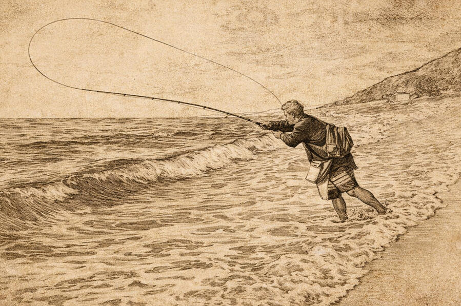
Why Use a Two-Handed Fly Rod for Surf FishingA mechanical justification for overhead casting in a distance-driven, wind-dominated, endurance environmentSurf fishing is a distance, wind, and endurance problem, and the rod you choose determines whether you can solve those problems efficiently.A two-handed fly rod is not chosen because it is different. It is chosen because it is mechanically correct for the surf.This article explains why, using only overhead casting mechanics, no Spey, no D-loops, no anchors.1. The Surf Is a Distance Fishery
The feeding lanes sit 50–110 feet off the beach, beyond the first trough and often behind the first bar.A two-handed rod makes that distance:
• easier
• repeatable
• sustainableThe longer lever multiplies tip speed with less effort, turning distance from a “sometimes” event into a baseline capability.2. Wind Is the Default ConditionOnshore wind is not an obstacle; it is the environment.A two-handed rod:
• stabilizes the stroke
• increases tip velocity
• drives heavier heads
• produces tighter, wind-cutting loops
You are not overpowering the wind; you are neutralizing it through leverage.3. The Longer Rod Elevates the Line Above TurbulenceSurf water moves in three directions at once:
• wave lift
• backwash
• side washA longer rod keeps the line higher during pickup and acceleration, reducing drag and preventing failed pickups.4. Heavy Lines Become Easy to CastSurf fishing requires:
• 350 - 500 grain heads
• sink tips
• weighted fliesA two-handed rod stabilizes these loads and smooths acceleration, preventing shock loading on the joints and allowing clean turnover without muscling the cast.5. You Can Fish Shallower and Stay SaferDistance from a shallow stance is a safety advantage.A two-handed rod allows you to:
• stand ankle deep instead of waist deep
• avoid drop-offs and collapsing bars
• maintain footing in shifting sand
You reach the same water without entering dangerous water.6. Less Fatigue, Less Joint Stress, More EnduranceThe mechanical advantage that matters most in the surfSurf fishing is an endurance environment. A two-handed overhead rod dramatically reduces fatigue and protects the joints by distributing load and generating line speed.A. Two Hands Split the LoadA single-hand rod forces all casting forces through:
• wrist
• elbow
• shoulderA two-handed rod distributes the load across:
• both hands
• both forearms
• both shoulders
• core rotation
• hips and legs
This eliminates the “single joint overload” that causes fatigue and breakdown.B. Leverage Reduces Required ForceA longer lever produces more tip speed with less muscular effort. You are not powering the cast; you are leveraging it.This protects:
• rotator cuff
• elbow tendons
• wrist flexors/extensorsC. The Lower Hand Removes Stress From the ShoulderThe lower hand drives rotation and stabilizes the rod. This reduces:
• shoulder impingement
• deltoid fatigue
• upper arm strain
The shoulder becomes a stabilizer, not a power source.D. Neutral Wrist PositionTwo-hand overhead casting keeps the wrist neutral and supported, reducing:
• tendonitis
• carpal tunnel flare
• wrist fatigueE. Core Driven Mechanics Increase EnduranceTwo-hand overhead casting naturally recruits:
• hips
• obliques
• torso rotation
• leg drive
Large muscle groups = long sessions without breakdown.F. Reduced Resistance From the SurfA longer rod elevates the line above turbulence, reducing drag during pickup and forward stroke.
Less resistance = less fatigue.7. Overhead Casting Becomes Simpler, Not More ComplexTwo-handed overhead casting is:
• linear
• compact
• stable
• intuitiveBottom LineA two-handed fly rod is chosen for surf fishing because it is the mechanically correct tool for:
• distance
• wind
• moving water
• heavy lines
• safety
• endurance
• joint preservationIt is not a niche technique. It is the right tool for the environment.

The Three Overhead Power Sources in Surf CastingHow a two-handed rod actually generates force in a surf casting environmentA two-handed overhead cast in the surf is powered by three mechanical sources.These sources appear in every clean, stable, repeatable cast, regardless of angler style or rod model:
1. Top hand rotation (fulcrum)
2. Bottom hand pull
3. Body rotation (hips + torso)These are not techniques. They are the mechanical realities of how a two-handed rod produces line speed and loop stability in wind and moving water.1. Top Hand Rotation (fulcrum)The rod’s steering and timing input
In a correct overhead cast, the top hand provides:
• rod angle
• stroke length
• casting plane
• timing of rotationIt governs the path of the rod tip, not the power of the cast.
When top hand rotation is the dominant force, the cast shows:
• wide loops
• collapsing tip path
• shoulder overload
• inconsistent turnoverWhen top hand rotation is used as a control input, the cast shows:
• clean tracking
• stable loop geometry
• predictable timing
• consistent direction in wind
The top hand is the precision source.2. Bottom Hand PullThe primary power source in a two-handed overhead cast.In a mechanically efficient cast, the bottom hand supplies most of the acceleration.Its role is to:
• drive the rod butt
• deepen the rod load
• stabilize heavy heads
• maintain a compact stroke
• produce smooth, linear powerWhen the bottom hand is under-expressed, the cast shifts into top hand dominance, which results in:
• shoulder fatigue
• wide loops
• reduced penetration
• inconsistent line speedWhen the bottom hand is fully expressed, the cast gains:
• deeper rod load
• tighter loops
• higher line speed
• cleaner turnover in wind
The bottom hand is the power source.3. Body Rotation (Hips + Torso)
The stabilizer and endurance engineIn a stable overhead cast, the body contributes a small but critical rotational component.Body rotation provides:
• mass behind the stroke
• rod path stability
• balance in moving water
• reduced arm strain
• consistent accelerationWhen body rotation is absent, the cast becomes:
• arm driven
• timing sensitive
• fatiguing
• unstable under loadWhen body rotation is present, the cast becomes:
• repeatable
• efficient
• balanced
• resistant to surf turbulence
The body is the endurance source.How the Three Sources Combine in a Correct CastA mechanically sound overhead surf cast expresses the three sources in this sequence:1. Body rotation initiates the stroke (sets direction and stabilizes the rod)2. Bottom hand pull accelerates the rod (creates the majority of the load and line speed)3. Top hand rotation completes the stroke (sets loop shape and timing)This sequence produces:
• high line speed
• tight, wind-cutting loops
• stable turnover
• minimal fatigue
• consistent distanceEvery clean overhead cast in the surf follows this pattern, whether the angler is conscious of it or not.Failure Patterns (Described Mechanically, Not Instructionally)1. Top hand dominanceThe cast becomes shoulder driven, loops widen, and the rod tip collapses.2. Delayed bottom hand engagementThe rod fails to load deeply, and line speed remains low.3. Locked torsoThe cast becomes arm-only, timing degrades, and fatigue accelerates.4. Early rotationThe rod tip dips, producing tailing loops and unstable turnover.Each failure corresponds to a breakdown in one of the three power sources.Why These Sources Matter in the SurfThe surf amplifies mechanical flaws through:
• wind shear
• wave lift
• backwash
• heavy line systems
• unstable footingA cast built on the three power sources remains stable under these conditions because:• the body stabilizes
• the bottom hand powers
• the top hand controlsThis is the mechanical core of overhead surf casting.Bottom LineA two-handed overhead cast in the surf expresses three power sources:
1. Top hand rotation — control
2. Bottom hand pull — power
3. Body rotation — stability and enduranceThese are the mechanical realities of how a two-handed rod generates line speed and loop stability in a surf environment.
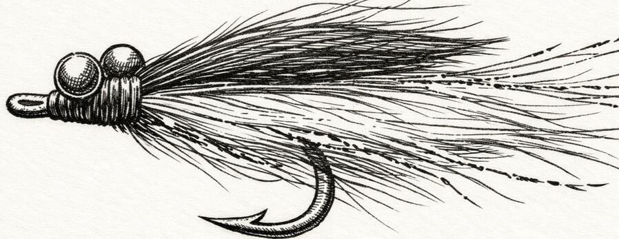
THE CASTING LANEThe straight, shoulder-aligned corridor that runs from the end of the backcast to the point where the fly landsThe casting lane is the structural boundary of the two-handed overhead surf cast. It is not conceptual. It is a literal geometric corridor the line must occupy in both directions.The lane runs:
from the apex of the backcast to the exact point where the fly lands on the forward cast.Every clean cast lives inside this corridor. Every failure is a lane violation.What the Casting Lane Actually IsThe casting lane is:
• a straight corridor
• 24–30 inches wide
• directly in front of the casting shoulder
• extending backward to the apex
• extending forward to the fly’s landing point
• on a single, consistent vertical planeThis corridor defines the rod tip path, the loop plane, and the trajectory of the entire stroke.The Lane’s Rear Boundary: The Backcast ApexThe lane begins when the backcast straightens and the apex forms.This apex must be:
• directly behind the casting shoulder
• 8–12 ft above the water
• on the same plane as the forward strokeThis is the origin of the lane.
If the apex forms off lane, the slide collapses, the forward stroke compensates, and the cast dies.The Lane’s Forward Boundary:The Fly’s Landing Point
The lane ends at the exact point where the fly lands.This point must be:
• directly in front of the casting shoulder
• on the same vertical plane as the apex
• on the same horizontal plane as the rod tip
• aligned with the forward trajectoryThis is the terminus of the lane.
If the fly lands off-lane, the loop was off-plane.The Lane Is a Straight Line Between These Two PointsThe lane is the straight line connection between:Backcast apex → Fly landing point
This line defines:
• tip path
• loop geometry
• slide direction
• rotation plane
• stop plane
• trajectory
Any deviation from this line is a lane violation.Lane Width: 24–30 InchesThe lane is narrow because:
• the rod tip must travel straight
• the loop must remain symmetrical
• the apex must remain aligned
• the slide must preserve tension
• the stop must occur on a single planeNarrower than 24 inches → rod tip deviates, loop collapses. Wider than 30 inches → line drifts off axis, apex breaks.The lane is a fixed geometric constraint.Lane Alignment: Shoulder Based, Not Target BasedThe lane is aligned to the casting shoulder, not the target.The target is reached by trajectory, not by shifting the lane.If the lane is pointed at the target:
• rotation becomes off axis
• tension breaks
• apex collapses
• loop twists
The lane is a mechanical alignment, not a directional aim.Lane Integrity Through the Stroke SequenceThe lane must be preserved through all phases:A. Aerialized Retensioning
The Snake Roll Pickup flips the system forward into the lane.B. High Backcast
The apex forms in the lane, directly behind the shoulder.C. Drift
Drift raises the rod without leaving the lane.D. Slide
Slide moves forward on the same plane, preserving lane geometry.E. Translation
Translation drives the rod butt forward in the lane.F. Rotation
Rotation occurs around the lane, not across it.G. Stop
The stop terminates rotation on the lane’s plane, defining loop geometry.
Lane integrity is the backbone of the entire stroke.Lane Violations and Their Mechanical Signatures1. Off Lane Backcast
Apex forms sideways → tension collapses → slide fails.2. Off Lane Slide
Slack appears → loop opens → turnover slows.3. Off Lane Rotation
Loop twists → bottom leg rolls sideways → instability in wind.4. Off Lane Stop
Apex drops → trajectory flattens → distance collapses.
Every lane violation has a visible loop signature.Why the Lane Determines DistanceDistance requires:
• straight tip path
• high apex
• level slide
• late rotation
• high stopAll five depend on lane integrity from:apex → fly landing point
If the lane breaks anywhere along that line, distance collapses.Bottom Line
The casting lane is the straight, shoulder-aligned corridor that runs:
from the apex of the backcast to the exact point where the fly lands.It is:
• 24–30 inches wide
• vertically consistent
• plane consistent
• tension preserving
• the structural foundation of the entire strokeEvery clean overhead surf cast lives inside this lane. Every failure is a lane violation.
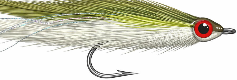
THE TWO-HANDED OVERHEAD SURF WIND SYSTEMCrosswind, Headwind, and Tailwind Mechanics for Long Rod Overhead CastingPurpose
This doctrine defines the operational wind control system for two-handed overhead casting in surf environments. Unlike Spey casting, which stabilizes itself through the anchor, D-loop, and water tension, the overhead discipline has no external stabilizing structure.Wind becomes the dominant environmental force acting on the rod, line, and loop. This system establishes the mechanical, geometric, and timing adjustments required to maintain loop integrity, trajectory control, and rod tip path discipline under wind load.1. Wind as a Structural Force
Wind affects overhead casting in three primary ways:
1. Rod tip path deviation
2. Loop deformation
3. Trajectory collapse or stallLong rods (11–14 ft) amplify these effects because:
• the tip travels farther through space
• the rod plane is more exposed
• the stroke arc is larger
• the release window is narrowerWind is not a nuisance variable. It is a structural component of the environment that must be integrated into every phase of the cast.2. Crosswind Mechanics
Crosswind is the most destabilizing wind direction for overhead casting. It attempts to collapse the rod plane, push the loop off axis, and force compensatory body rotation.2.1 Rod Plane Adjustment
The rod plane must be canted into the wind to maintain a straight line tip path. The required cant increases with:
• wind speed
• rod length
• loop tightness
• line mass
A 12–14 ft rod requires more cant than a 9–10 ft rod due to increased tip exposure.2.2 Body Geometry
The torso rotates slightly into the wind while the hips remain neutral. This prevents:
• over rotation
• tip path drift
• loop collapse2.3 Loop Shape
Crosswind requires a tight, high-energy loop. This is produced through:
• late rotation
• compact stroke arc
• disciplined tip path2.4 Release Timing
The release must occur earlier than in neutral wind conditions to prevent the wind from pushing the line off-axis.3. Headwind Mechanics
Headwind is the most punishing direction for distance but the most predictable mechanically.3.1 Trajectory
Headwind requires a low line trajectory. High trajectories stall. Mid trajectories deform. Low trajectories penetrate.3.2 Loop Shape
The loop must be:
• tight
• narrow
• high energyThis is achieved through:
• late rotation
• compact stroke
• high line speed3.3 Mass and Taper
Heavier heads and wind-cutting tapers perform better in headwind. Underweighted lines collapse.3.4 Release Timing
The release must be late, driving the line downward into the wind.4. Tailwind Mechanics
Tailwind is the easiest wind direction for distance but the most deceptive for loop stability.4.1 Trajectory
Tailwind requires a high line trajectory to maximize carry and drift.4.2 Loop Shape
The loop can be slightly open to maintain stability. Overly tight loops destabilize when pushed from behind.4.3 Release Timing
The release must be early, allowing the wind to carry the line forward.4.4 Stroke Length
A longer stroke is beneficial because the wind assists the line.5. Wind Driven Line Behavior
Wind interacts with line systems through:
• diameter
• taper
• mass distribution
• head length5.1 Diameter
Thinner lines penetrate wind more effectively. Thicker lines deform.5.2 Taper
Aggressive front tapers cut wind. Long, gradual tapers stabilize loops.5.3 Head Length
Longer heads resist wind deformation better than short heads.5.4 Running Line
Mono excels in wind but is harder to manage in surf. Coated running lines are easier to handle but less wind efficient.6. Surf Specific Wind Behavior
Wind in the surf is shaped by:
• wave-driven turbulence
• salt air density
• shoreline thermals
• gust patterns
• lateral shearThese factors require:
• stance adjustments
• rod plane adjustments
• trajectory modifications
• timing correctionsThe Gulf Coast produces lateral shear winds that collapse rod planes unless the caster compensates with body geometry and rod plane cant.7. Common Failures and Corrections7.1 Plane Collapse
Cause: Crosswind overpowering rod plane. Correction: Increase rod plane cant + tighten loop7.2 Dumped Trajectory
Cause: Late release in headwind. Correction: Earlier release + lower trajectory7.3 Over Rotation
Cause: Compensating with torso instead of rod plane Correction: Neutral hips + controlled shoulder rotation7.4 Loop Destabilization
Cause: Wind deforming loop shape Correction: Adjust loop geometry through stroke arc and rotation timing7.5 Backcast Collapse
Cause: Wind pushing line off axis Correction: Cant rod plane into wind + tighten backcast loopConclusion
The Two-Handed Overhead Surf Wind System establishes the operational framework required to maintain mechanical integrity under real surf conditions. By defining how rod plane control, loop geometry, trajectory selection, and release timing must adapt to crosswind, headwind, and tailwind forces, this doctrine converts the overhead stroke from a laboratory mechanic into a field-ready system.Wind is not a variable to be endured; it is a structural component of the environment that must be integrated into every phase of the cast. When applied correctly, this system preserves tip-path discipline, stabilizes loop formation, and maintains line speed under conditions that routinely cause conventional overhead casting to collapse.It is the environmental backbone of the two-handed overhead discipline.
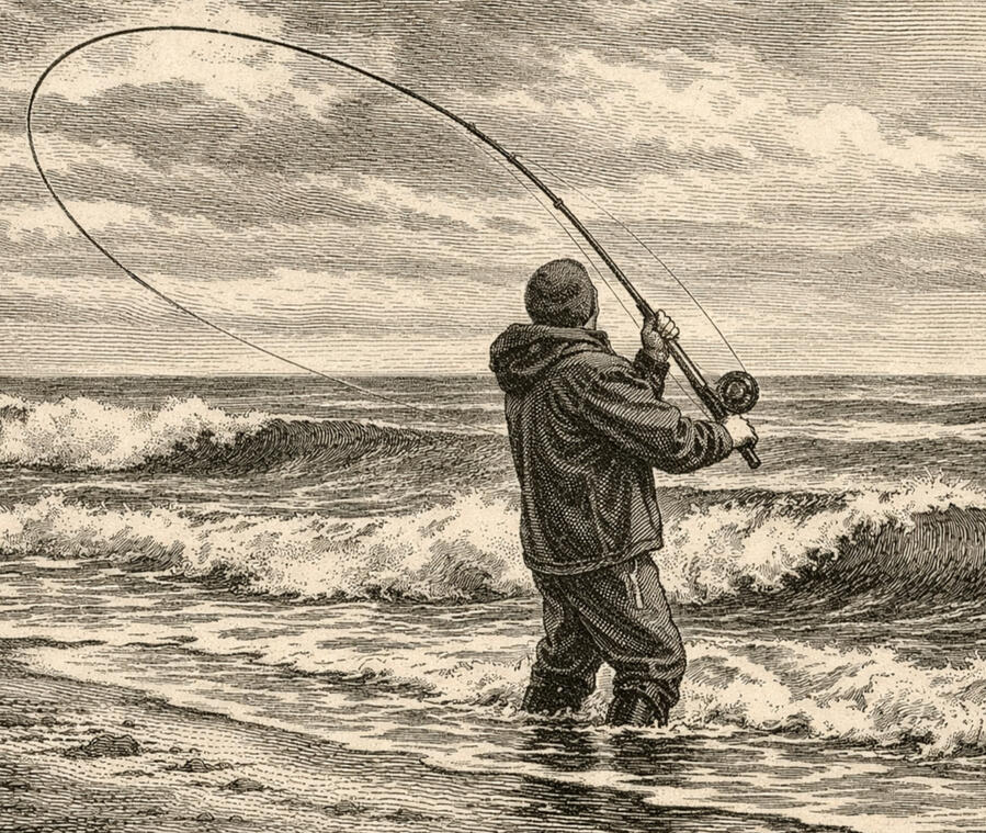
THE MECHANICS OF LINE SPEED IN TWO-HANDED OVERHEAD CASTINGLine speed is the governing variable in two-handed overhead casting. It determines:
• loop shape
• apex height
• turnover stability
• wind penetration
• distance ceilingEvery other variable- rod length, head mass, stroke length, rotation timing- exists to serve line speed.This article defines line speed mechanically and explains how it is generated, preserved, and lost in the surf environment.1. What Line Speed Actually Is (Mechanical Definition)Line speed is the velocity of the fly line at the moment of loop formation. It is not:
• how fast your hands move
• how hard you “hit” the rod
• how fast the rod tip travels in translationLine speed is created at the instant of rotation, when the rod unloads, and the tip path transitions from linear (translation) to angular (rotation).Mechanically:
Line speed = rod tip velocity at the moment of loop formation.
Everything else is setup.2. The Three Inputs That Create Line SpeedThree mechanical inputs produce line speed:A. Translation (the setup)
This is the straight-line motion of the rod before rotation. Its purpose is:
• to position the rod
• to pre-load the blank
• to establish a clean tip path
Translation does not create line speed. It creates the conditions for line speed.B. Rotation (the engine)
Rotation is where line speed is generated. The rod tip accelerates through an arc, unloads, and transfers stored energy into the line.Rotation must be:
• late
• fast
• compact
• decisive
Early rotation kills line speed. Late rotation amplifies it.C. Rod Recovery (the multiplier)A fast-recovering blank increases line speed by:
• reducing tip wobble
• tightening the loop
• preserving energy
• stabilizing turnover3. How Line Speed Differs Between Spey and Overhead CastingSpey Casting
Line speed is distributed across:
• D-loop mass
• anchor tension
• deeper rod load
Spey line speed is mass-driven.Overhead Casting
Line speed is concentrated in:
• tip velocity
• late rotation
• compact load
• fast recoveryOverhead line speed is tip driven.
This is why overhead requires:
• more precision
• more timing
• more rod speed
• more apex controlSpey gives you distance with less effort. Overhead gives you wind authority and apex geometry.4. The Five Mechanical Factors That Control Line Speed1. Rotation Timing
Late rotation produces maximum line speed. Early rotation bleeds energy into the air.2. Tip Path Integrity
A straight, rising tip path preserves energy. A dipping or convex tip path destroys it.3. Head Mass
Heavier heads load the rod deeper and produce more line speed, up to the rod’s limit. Too heavy = collapse. Too light = no load.4. Rod Recovery Rate
Fast recovery = tight loop = preserved line speed. Slow recovery = wide loop = lost energy.5. Stroke Length
Longer stroke = more room for acceleration. Short stroke = compact but requires perfect timing.5. How Wind Interacts with Line SpeedWind does not “steal” line speed. Wind exposes insufficient line speed.Crosswind
Requires:
• tighter loop
• higher apex
• faster rotationOnshore Wind
Requires:
• more line speed
• more turnover authority
• more head massTailwind
Allows:
• higher apex
• longer shoot
• reduced rotation force
Line speed is the only variable that consistently defeats wind.6. How Line Speed Fails (Failure Modes)A. Early Rotation
The most common failure. The rod unloads too soon → low line speed → collapsing apex.B. Tip Path Deviation
Any wobble, dip, or convexity bleeds energy.C. Over Rotation
Too much arc → wide loop → low line speed.D. Under Rotation
Too little arc → incomplete turnover → unstable flight.E. Insufficient Load
Head too light → rod never stores energy → no line speed.Bottom Line
Line speed is created by:
• late rotation
• fast recovery
• clean tip path
• correct head mass
• disciplined stroke geometryApex, loop stability, and distance all depend on line speed. Master line speed, and the entire overhead system becomes predictable, repeatable, and wind-dominant.
TIP PATH GEOMETRY IN TWO-HANDED OVERHEAD CASTINGTip path geometry is the governing variable behind loop shape, line speed, apex height, and turnover authority in two-handed overhead casting.Every mechanical outcome, good or bad, can be traced back to the path the rod tip travels during the stroke.This article defines tip path geometry mechanically and explains how it controls the entire overhead system.1. What Tip Path Geometry Actually Is
Tip path geometry is the three-dimensional trajectory the rod tip travels from the start of translation to the end of rotation.It determines:
• loop shape
• loop stability
• apex height
• line speed
• turnover behavior
• wind penetrationThe rod tip is the only part of the system the line “sees.” The line simply follows the path the tip traveled.Mechanically
Tip path = loop geometry. Loop geometry = flight behavior.2. The Three Phases of Tip Path GeometryA. Linear Tip Path (Translation)The rod tip moves straight, level, or slightly rising. Purpose:
• establish the casting plane
• pre-load the rod
• set the loop’s initial geometry
A clean linear path is mandatory for a tight, stable loop.B. Angular Tip Path (Rotation)The rod tip pivots through an arc. Purpose:
• generate line speed
• form the loop
• define loop width
Rotation must be:
• late
• compact
• decisiveC. Recovery Tip Path (Post Rotation)The rod straightens and rebounds. Purpose:
• stabilize the loop
• preserve line speed
• prevent tip wobble
Fast recovery = stable loop. Slow recovery = unstable loop.3. The Four Tip Path Shapes and Their Outcomes1. Straight Line Tip PathThe ideal geometry.
Produces:
• tight loop
• high line speed
• stable apex
• wind authority
This is the geometry of a mechanically correct cast.2. Rising Tip PathTip path ascends slightly during translation.
Produces:
• higher apex
• longer flight
• better wind penetration
• improved turnover
This is the geometry used for distance and surf conditions.3. Convex Tip PathTip path bulges outward (rod tip travels too far from the casting plane).
Produces:
• wide loop
• low line speed
• unstable turnover
• poor wind performance
This is the geometry of early rotation or excessive arc.4. Dipping Tip PathTip path drops during translation or early rotation.
Produces:
• tailing loop
• apex collapse
• line crash
• turnover failure
This is the geometry of premature rotation or uneven acceleration.4. How Tip Path Geometry Controls Loop ShapeLoop shape is not a mystery. It is a direct mechanical consequence of tip path.
Straight tip path → tight loop
Convex tip path → wide loop
Dipping tip path → tailing loop
Rising tip path → high apex loop
There is no exception to this.5. How Tip Path Geometry ControlsLine Speed
Line speed is created at the moment of rotation, but tip path determines how efficiently that speed is preserved.Clean tip path = preserved line speedDeviated tip path = lost line speed
Any wobble, dip, or convexity bleeds energy.This is why overhead casting demands:
• disciplined translation
• late rotation
• fast recoveryTip path integrity is the difference between a cast that flies and a cast that collapses.6. How Wind Interacts with Tip Path GeometryWind does not change the physics. Wind exposes flaws in tip path geometry.Crosswind
Requires:
• straighter tip path
• tighter loop
• higher apexOnshore Wind
Punishes:
• convex tip path
• wide loops
• early rotationTailwind
Allows:
• rising tip path
• longer shoot
• extended apex
Wind performance is tip path performance.7. Tip Path Failure ModesA. Early Rotation
Tip path dips → tailing loop → apex collapse.B. Excessive Arc
Tip path becomes convex → wide loop → low line speed.C. Uneven Acceleration
Tip path wobbles → unstable loop → poor turnover.D. Over Translation
Tip path drifts → delayed rotation → incomplete turnover.E. Under Translation
Tip path shortens → insufficient load → weak loop.
Every failure in overhead casting is a tip path failure.Bottom LineTip path geometry is the foundation of two-handed overhead casting. It determines:
• loop shape
• line speed
• apex height
• turnover authority
• wind performanceA clean, rising, straight-line tip path, followed by late, decisive rotation, produces the tight, stable, wind-dominant loops required for surf casting.Master tip path geometry, and the entire overhead system becomes predictable, repeatable, and mechanically controlled.